- 您现在的位置:买卖IC网 > Sheet目录1210 > DK-114N-3 (Luminus Devices Inc)KIT DEV PHLATLIGHT CBT/PT LED
�� �
�
�PhlatLight� ?� DK-114N� Series� Development� Kit� Manual�
�5.� Rotate� all� of� the� current� controlling� POTs� (located� at� “P1”,�
�tor� in� Ohms.� The� sense� resistor� value� is� 0.005� Ω.�
�The�
�“P2”� and� “P3”� on� the� control� board� and� at� “P1”� on� the� driv-�
�er� board)� counter-clockwise� until� they� stop.� The� imbedded�
�arrow� should� point� towards� the� “10”� on� the� POT.� The� POT�
�is� now� set� at� the� minimum� current� setting.�
�6.� The� evaluation� kit� is� now� ready� to� be� powered� on.� Turn� on�
�the� power� supply.� The� supply� will� draw� a� small� amount� of�
�power.�
�7.� To� turn� on� any� channel,� open� the� enable� pin� by� removing�
�the� jumper.� Both� the� fan� on� the� heat� sink� and� the� LED� will�
�power� on.�
�Operating� Instructions�
�There� are� multiple� different� ways� the� PhlatLight� DK-114N� De-�
�velopment� Kit� can� be� operated.� The� LEDs� can� be� driven� in� con-�
�tinuous,� current� controlled� mode� via� on� board� POTs� or� through�
�an� external� analog� voltage.� Additionally,� each� channel� has� in-�
�puts� for� an� external� function� generator� signal� to� pulse� the� LEDs�
�and� is� capable� of� pulsing� at� frequencies� of� greater� than� 40kHz.�
�1.� To� change� the� current� when� either� the� interface� board� or�
�driver� board� is� enabled,� rotate� the� on� board� POT.� Each�
�POT� will� only� function� when� enabled� on� the� interface�
�board.� Clockwise� rotation� increases� the� current,� while�
�counter-clockwise� rotation� will� decrease� the� current.�
�2.� To� change� the� current� when� the� external� adjust� is� enabled,�
�attach� a� 0-5V� signal� to� the� ADJ� test� points.� These� are� la-�
�beled� “T3”,� “T4”,� “T7”,� “T8”,� “T11”� and� “T12”.� Each� test�
�point� is� also� labeled� with� either� “GND”� or� “ADJ”.� When�
�hooking� up� the� 0-5V� signal,� ensure� that� the� ground� cable� is�
�attached� to� the� “GND”� test� point� and� the� positive� cable� is�
�attached� to� the� “ADJ”� test� point.�
�The� current� to� the� LED� will� adjust� with� the� voltage� signal.�
�output� value� will� the� be� current� going� to� the� LED� in� amps�
�(A).�
�Sense� Resistor� Test� Studs�
�Figure� 17:� Sense� resistor� location� on� driver� board�
�18�
�16�
�14�
�12�
�10�
�8�
�6�
�4�
�2�
�0�
�A� higher� voltage� corresponds� with� a� higher� current.�
�10�
�30�
�50�
�70�
�90�
�V� Sense�
�I� LED� =� ---------------�
�It� is� recommended� not� to� exceed� a� 5V� signal,� as� compo-�
�nents� may� overheat.�
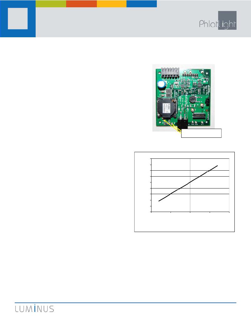
�3.� To� measure� the� current� going� to� the� LED,� use� a� volt� meter�
�and� measure� the� voltage� across� the� sense� resistor� on� the�
�driver� board.� For� ease� of� probing,� two� test� studs� have� been�
�placed� to� the� left� and� right� of� “R15”.� Figure� 17� shows� the�
�location� of� the� test� studs� on� the� driver� board.� Figure� 18�
�shows� a� conversion� plot� between� the� sense� resistor� voltage�
�and� the� current� going� to� the� LED.� The� current� can� also� be�
�calculated� by� the� following� formula:�
�Equation� 1�
�R� Sense�
�where� V� Sense� is� the� voltage� measured� across� the� sense� re-�
�sistor� in� Volts� (V)� and� R� Sense� is� the� value� of� the� sense� resis-�
�V� Sense� (mV)�
�Figure� 18:� LED� Current� vs.� Vsense� voltage�
�4.� To� modulate� the� LEDs� through� PWM,� connect� a� function�
�generator� to� the� test� points� labeled� “PWM”� and� “GND”.�
�These� test� points� are� also� labeled� “T1”,� “T2”,� “T5”,� “T6”,�
�“T9”� and� “T10”.� The� pulse� output� should� be� set� to� 0-5V,�
�where� 5V� represents� off� and� 0V� represents� on.�
�Proper� operation� is� best� monitored� by� using� a� photo� detec-�
�tor� to� observe� the� light� output� from� the� LED.�
�Figures� 16� -� 18� show� plots� of� typical� waveforms.� The� device�
�under� test� was� a� blue� CBT-54� run� at� 14A� and� 50%� duty� cycle� at�
�30kHz.� Actual� waveforms� will� depend� on� the� specific� driver�
�?� 2009� Luminus� Devices,� Inc.� -� All� Rights� Reserved�
�Page� 7�
�发布紧急采购,3分钟左右您将得到回复。
相关PDF资料
DK-136M-3
KIT DEV PHLATLIGHT CBT/PT LED
DK-409N-1
KIT DEV PHLATLIGHT CBM360 LED
DK-414N-4
KIT DEV PHLATLIGHT CBM380 LED
DK-PS21765
KIT DEV INTERFACE IPM MINIDIP
DK-PS21965
KIT DEV INTERFACE IPM MINIDIP
DK-RV-1.8-TRK-33
EVAL KIT SQUIGGLE MOTOR + SENSOR
DK-SI-4S100G2N
KIT DEV STRATIX IV TRANSCEIVER
DLP-2232H
MODULE USB ADAPTER FOR FT2232H
相关代理商/技术参数
DK115199
制造商:TE Connectivity 功能描述:
DK115201
制造商:TE Connectivity 功能描述:
DK115202
制造商:TE Connectivity 功能描述:
DK116399
制造商:TE Connectivity 功能描述:
DK116664
制造商:TE Connectivity 功能描述:
DK117439
制造商:TE Connectivity 功能描述:
DK11XEA100K86RAH01
功能描述:CAP CER 10PF 250V SL NONSTND SMD 制造商:murata electronics north america 系列:DK1 包装:剪切带(CT) 零件状态:在售 电容:10pF 容差:±10% 电压 - 额定:250V 温度系数:SL 工作温度:-40°C ~ 125°C 特性:- 等级:X1,Y1 应用:安全 故障率:- 安装类型:表面贴装,MLCC 封装/外壳:非标准型 SMD 大小/尺寸:0.315" 长 x 0.236" 宽(8.00mm x 6.00mm) 高度 - 安装(最大值):- 厚度(最大值):0.098"(2.50mm) 引线间距:- 引线形式:鸥翼型 标准包装:1
DK11XEA100K86RBH01
功能描述:CAP CER 10PF 300V SL NONSTND SMD 制造商:murata electronics north america 系列:DK1 包装:剪切带(CT) 零件状态:在售 电容:10pF 容差:±10% 电压 - 额定:300V 温度系数:SL 工作温度:-40°C ~ 125°C 特性:- 等级:X1,Y1 应用:安全 故障率:- 安装类型:表面贴装,MLCC 封装/外壳:非标准型 SMD 大小/尺寸:0.315" 长 x 0.236" 宽(8.00mm x 6.00mm) 高度 - 安装(最大值):- 厚度(最大值):0.098"(2.50mm) 引线间距:- 引线形式:鸥翼型 标准包装:1